General Parameters for Fiber Laser Marking Machine Software (EzCAD)
Views :
Update time : 2024-11-25
Below, we introduce some common EzCAD parameters for fiber laser marking machines. These parameters are suitable for most marking tasks. The main areas to set up are listed below:
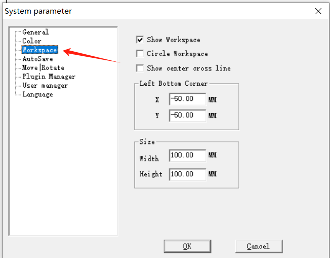
1. Workspace Parameters
These parameters are used to define the marking area and correspond to the field lens size:
- Field Lens 175:
- Bottom-right corner: X = -87.5, Y = -87.5
- Dimensions: Height = 175.00, Width = 175.00
- Field Lens 150:
- Bottom-right corner: X = -75, Y = -75
- Dimensions: Height = 150.00, Width = 150.00
- Field Lens 110:
- Bottom-right corner: X = -55, Y = -55
Dimensions: Height = 110.00, Width = 110.00
2. System Parameters
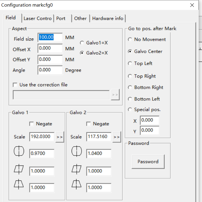
These settings also correspond to the field lens size:
- Field Lens 110: Area size = 110
- Field Lens 150: Area size = 150
- Field Lens 175: Area size = 175
3. Marking Parameters
Adjust the speed, power, and frequency to control the marking effect and efficiency:
- General Marking:
- Speed = 500, Power = 50, Frequency = 20
- Speed = 800, Power = 60, Frequency = 20
- Speed = 1200, Power = 80, Frequency = 20
- Black Marking on Stainless Steel:
Speed = 300, Power = 80, Frequency = 30
Notes:
- The field lens size determines the marking area. Ensure the parameters match the equipment in use.
- Adjust the marking parameters based on different materials, especially the combination of power and frequency.
- For black marking on stainless steel, reduce the speed and increase the frequency for a deeper color.
These settings are basic EzCAD parameters and can be applied to most marking tasks. For specific materials or processes, further adjustments and optimization are recommended.
Related News
Read More >>
 laser marking machine for meta
08 .01.2025
Laser Marking Machines for Metal in Singapore (2024 Guide)Singapore’s manufacturing and precision en...
 laser marking machine price in
08 .01.2025
Here's a detailed breakdown of laser marking machine prices in Pakistan (2024):Laser Marking Mac...
 HS code information of laser m
08 .01.2025
HS Codes for Laser Marking Machines1. General Laser Marking MachinesHS Code: 8479.89.90Description: ...
 20w fiber laser marking machin
08 .01.2025
Here's a concise breakdown of 20W fiber laser marking machine prices in 2025:Price Range (USD)Ca...


